
Appearance
Logic Trees
Once components are modeled, a logic tree similar to a Fault Tree from traditional modeling can be constructed. Logic trees allow for complex behavior to be easily modeled. An equivalent model using only Markov type modeling would require exponential growing and complex models. A standard use of L=logic trees would be in System diagram models with just two states and a special event used to evaluate Boolean logic. The two states are "Active" and "Failed", with a "Component Logic" event in the active state evaluating the assigned logic whenever a component diagram state changes. If the logic ever evaluates to false, then the current state shifts from "Active" to "Failed", as shown in the System diagram example in the Types of Diagrams: System section.
The following will give introductions to all the elements seen in the Fault Tree Editor and how to use them to construct a logic tree.
The Fault Tree editor consists of the Tools Window and the Editing Area.
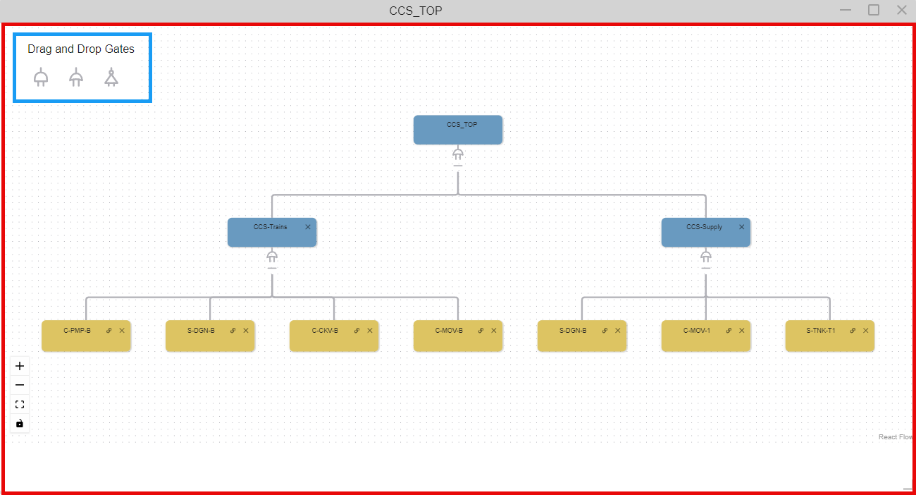
Each section will be explained in detail below.
Tools Window
Icon | Description |
|---|---|
| Logic Gates | |
 | Drag this icon to add an Or Gate to the Fault Tree |
 | Drag this icon to add an And Gate to the Fault Tree |
 | Drag this icon to add a Not Gate to the Fault Tree |
Editing Area
The logic trees consist of two basic elements: Logic Gates (Or and And) and Basic Events. The following sections will explain them in detail and how to model with them.
Logic Gates
Or Gate 
And Gate
Not Gate 
Adding a Gate
Option 1: From the Tools window, click and hold on to the gate you would like to add and drag it to the bottom of the desired gate in the Modeling Area until the gate highlights a light green, then release your mouse button.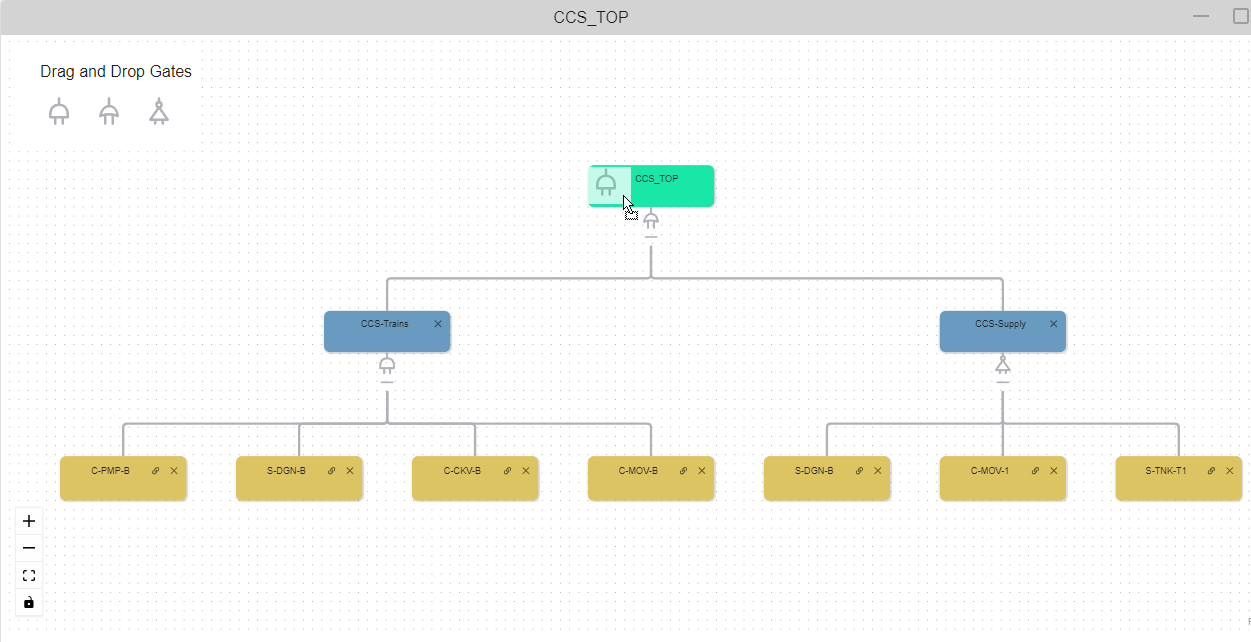
The gate will appear in the Editing Area under the branch you dragged it to.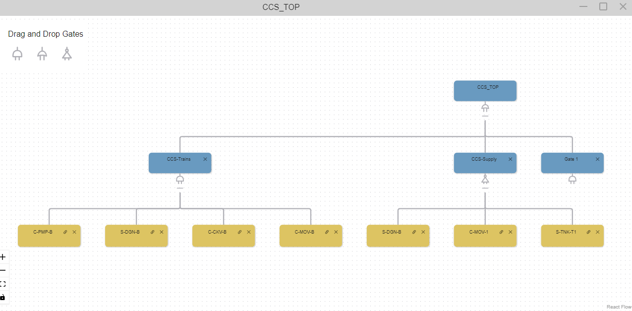
Option 2: In the Editing Area, right-click on the gate you would like to add a new gate under and select "Add Gate".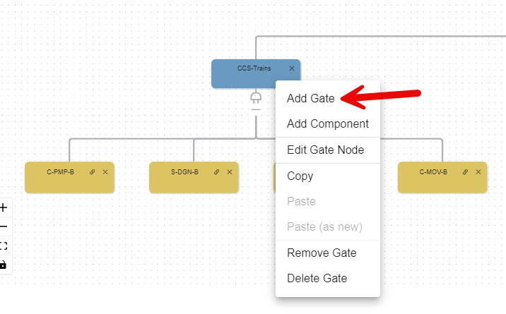
An Edit Forms/Gate Adder window will appear. Fill it out and click "SAVE". A description is optional.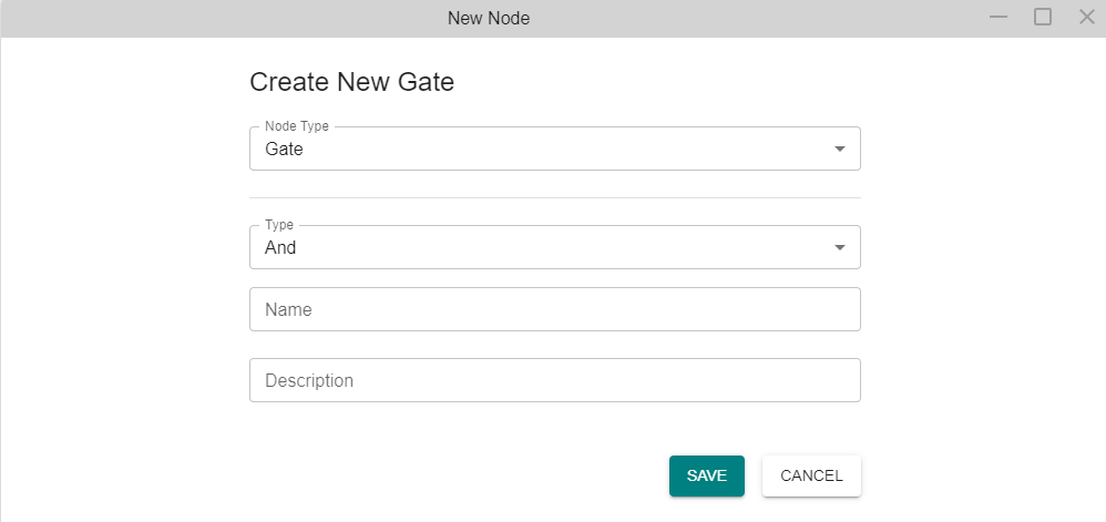
The gate will appear in the Editing Area under the branch you added it to.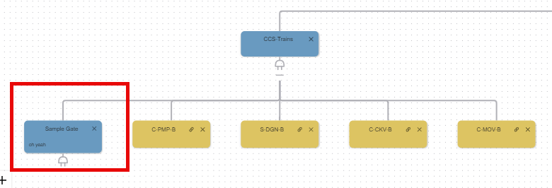
Editing a Gate
To edit a gate, right-click on the desired blue gate and select the option to "Edit Gate Node". 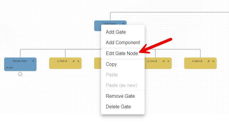
The Edit Gate Node window should appear. Click "SAVE" to confirm the changes.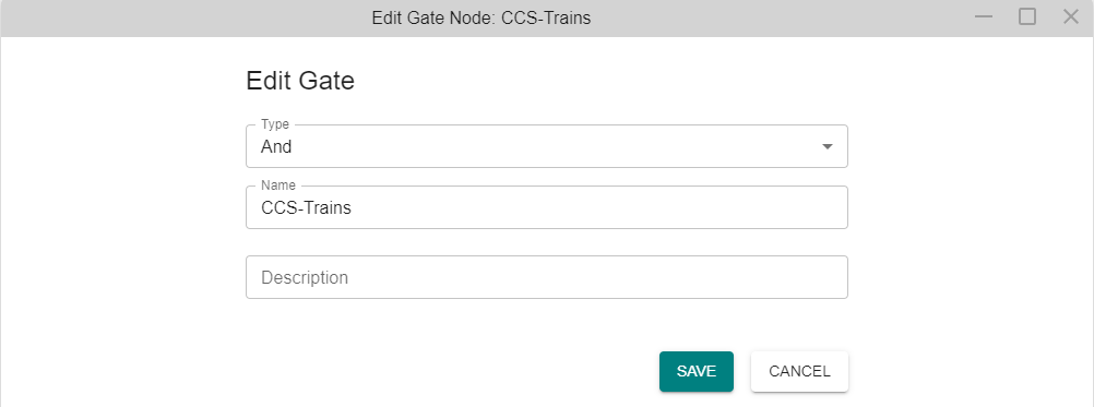
Deleting a Gate
Right-click on the gate and select the option to "Delete Gate" as shown below. This will delete the gate from all logic trees if you have previously copied and pasted that tree elsewhere. 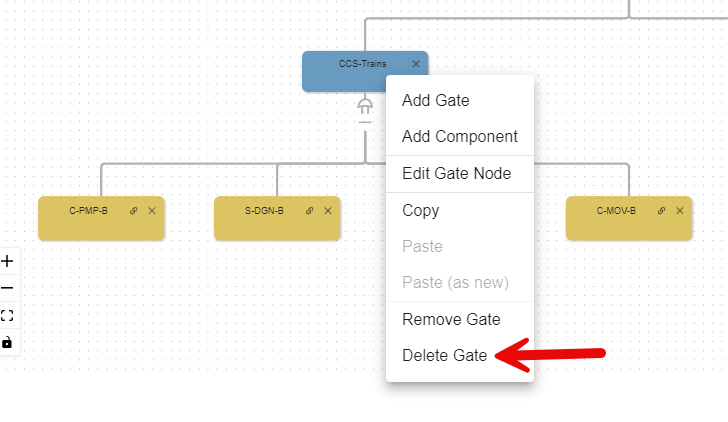
Removing a Gate
In the top right corner of the gate you would like to delete, click the [x] icon. Use caution as no confirmation window will appear.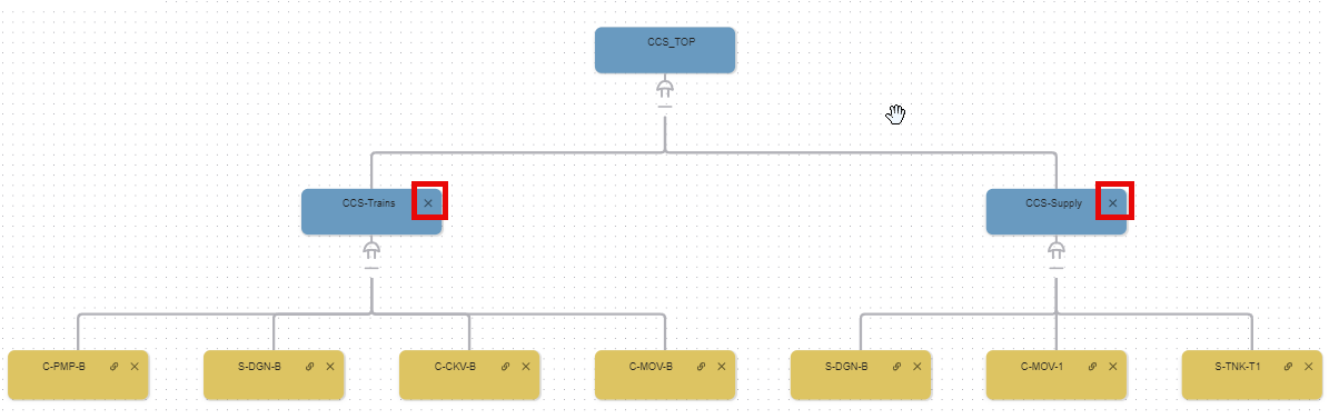
The gate will no longer be shown in the logic tree. You can also right-click and click "Remove Gate" for the same effect.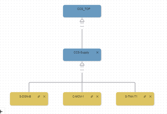
Basic Events

Adding a Basic Event
Option 1: Right-click on the gate node and click "Add Component" as shown below.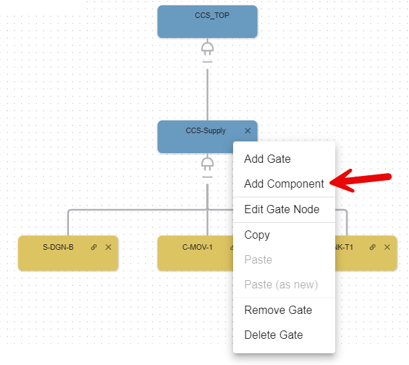
A window titled "New Node" will appear. Select the Component, or single state, Diagram from the dropdown list and then click "SAVE"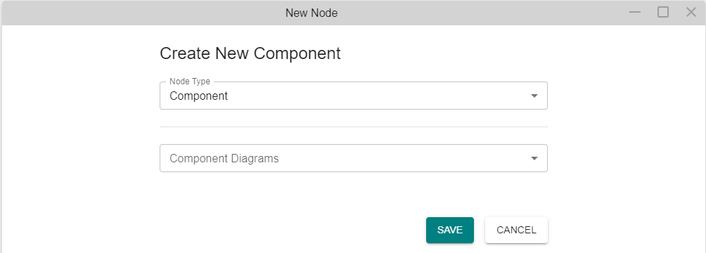
The Basic Event will appear in the Editing Area under the branch you added it to.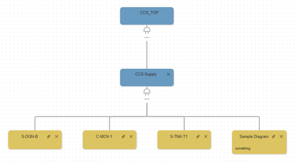
Option 2: From the Left Navigation Frame, expand the Diagrams section. Click and hold on to the Single State Diagram that you would like to add as a Basic Event to your logic tree. Then drag it to the Gate you would like it to be under. Once the Gate highlihgts green, release your mouse button. 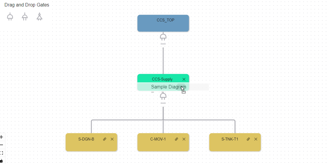
The Basic Event will appear in the Editing Area under the branch you added it to.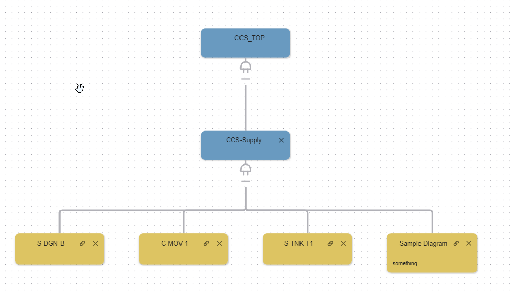
Editing a Basic Event
Option 1: Right-click on the Basic Event and click "Edit Component Node" from the pop up menu. 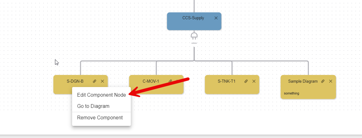
The Edit Component Node window will appear. After making any changes, click "SAVE". 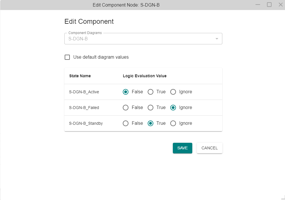
Option 2: Right-click on the Basic Event and click "Go to Diagram" from the pop up menu.
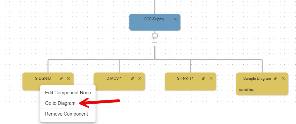
The Diagram window for the Basic Event will appear. You can edit the diagram from here.
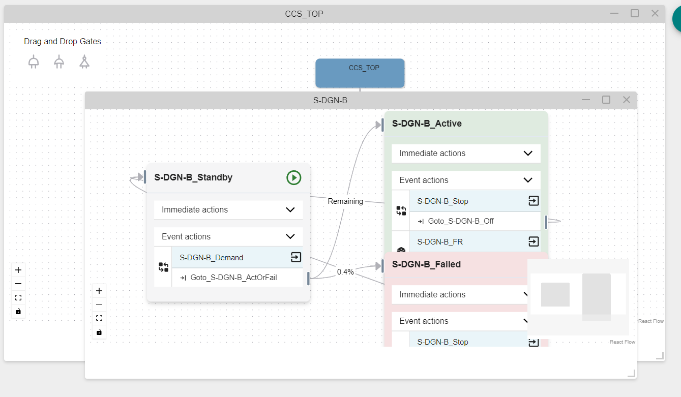
Option 3: Click on the "Link" icon at the top right of the Basic Event to the left of the [x].
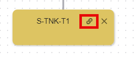
This opens up the Basic Event's diagram where it can be edited.
Deleting a Basic Event
Option 1:
In the top right corner of the Basic Event you would like to delete, click the [x] icon. Use caution as no confirmation window will appear.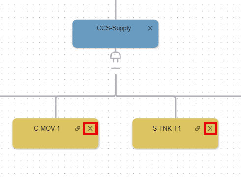
The Basic Event will no longer be shown in the logic tree. Clicking the [x] button removes the event fromt he tree but does not delete the corresponding diagram. 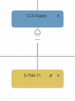
Option 2:
Right-click on the basic event and select "Remove Component". 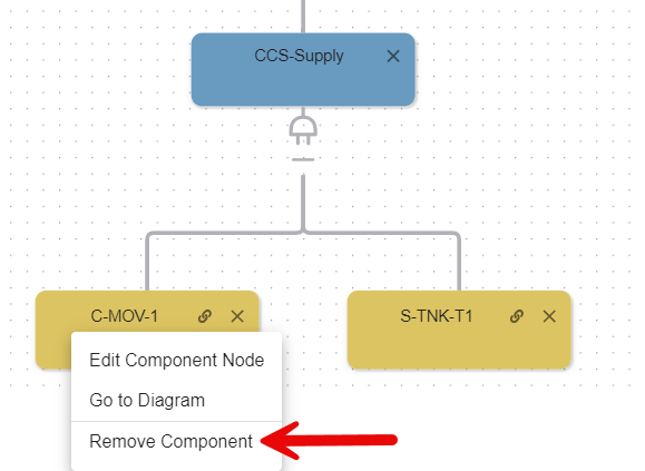
The Basic Event will no longer be shown in the logic tree.
Summary of Shared Symbols
Icon | Description |
|---|---|
 | Click to collapse the branches below the gate |
 | Click to expand the branches below the gate |
 | Click to go to the diagram of that component |